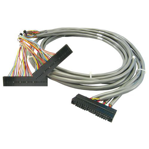
OPTO 22 - SNAP-HD-G4F6 _ Header cable for SNAP 32-channel digital modules and G4 digital racks, 6 ft. (1.8 m)
$300.00
- Brand
- OPTO 22
- SKU:
- SNAP-HD-G4F6
OPTO 22 - SNAP-HD-G4F6 _ Header cable for SNAP 32-channel digital modules and G4 digital racks, 6 ft. (1.8 m)
OPTO 22 - SNAP-HD-G4F6 _ Header cable for SNAP 32-channel digital modules and G4 digital racks, 6 ft. (1.8 m)Quick Specs:
- Header cable for SNAP 32-channel digital modules and G4 digital racks
- 6 ft. (1.8 m)
The SNAP-HD-G4F6 header cable has two uses: to connect a 32-channel digital module to older G4 digital I/O racks, and to connect a 32-channel digital output module to two SNAP-TEX-MR10-16C breakout boards in order to switch multiple loads up to 10 amps.
Connecting to G4 Digital I/O
The SNAP-HD-G4F6 header cable connects a SNAP 32-channel digital input module (SNAP-IDC-32) or output module (SNAP-ODC-32-SNK) to two G4 digital I/O racks. This allows older G4 (or even G1) digital output systems to be integrated with modern Opto 22 products like SNAP PAC controllers, SNAP Ethernet-based brains, and PAC Project software. This connection makes available the G4 output module's 3 amp switching capability, providing 12 times the 0.25 amp capability per point of the high-density digital modules.
The SNAP-HD-G4F6 connects one of the specified high-density digital modules with two G4PB16H, G4PB16HC, PB16H, or PB16HC racks. All G4 or G1 modules on the rack must be of the same type (input or output) and of the same logic voltage (5, 15 or 24 VDC). For a SNAP-IDC-32, logic voltage must be 15 or 24 volts, not 5 volts.
Note that the SNAP-IDC-32 returns positive-true logic, which is the inverse of the typical negative-true logic most modules return.
This cable cannot be used with a SNAP-ODC-32-SRC module when connecting to G4 racks.
See the SNAP TEX Cables and Breakout Boards Data Sheet for more information.
To connect the SNAP-IDC-32N module to G4 or G1 racks, see the SNAP-HD-G4F6N cable.
Connecting a 32-channel Output Module in order to Switch Loads to 10 A
The SNAP-HD-G4F6 header cable can also be used as a quick method to connect a 32-channel SNAP-ODC-32-SRC digital output module to two SNAP-TEX-MR10-16C breakout boards, each of which has 16 mechanical relays that can switch loads up to 10 amps.
The advantage of using this cable is that you don't have to wire the module to the breakout boards. Simply snap the cable onto the top of the module and then plug the cable's other ends into the header connectors on the two breakout boards.
Specifications:
Specifications are not currently available for this product.


