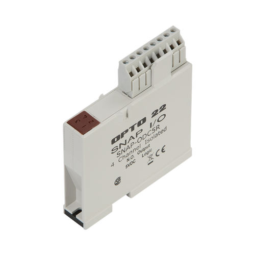
OPTO 22 - SNAP-ODC5R _ SNAP 4-Ch Reed Relay Digital (Discrete) Output Module, Normally Open
- Brand
- OPTO 22
- SKU:
- SNAP-ODC5R
OPTO 22 - SNAP-ODC5R _ SNAP 4-Ch Reed Relay Digital (Discrete) Output Module, Normally Open
OPTO 22 - SNAP-ODC5R _ SNAP 4-Ch Reed Relay Digital (Discrete) Output Module, Normally OpenQuick Specs:
- SNAP 4-Ch Reed Relay Digital (Discrete) Output Module
- Normally Open
Typical applications for these modules include analog signal and communication line multiplexing. Because of their low 10 VA rating, these modules are not recommended for inductive or capacitive loads (even very small loads) because the inrush current is likely to exceed the 10 VA rating.
IMPORTANT: Applications using 120 VAC are typically NOT suited to this module. If you are considering using this module for any application other than low-voltage purely resistive loads, see the detailed notes and rating curve in the data sheet, and call Pre-sales Engineering for specific guidance.
For many applications a better choice is the SNAP-OMR6-C module, which can handle a full 6 A at 0-250 VAC or 0-30 VDC.
Part of the SNAP PAC System, the module mounts on a SNAP PAC rack with a SNAP PAC brain or rack-mounted controller. Analog, digital, and serial I/O modules can all be on the same rack. Such an I/O unit is also well suited for PC-based control or for use as intelligent remote I/O for an Allen-Bradley Logix PLC system, such as ControlLogix, MicroLogix, or CompactLogix.
If you need Factory Mutual approved modules, see SNAP-ODC5RFM.
For easier, faster wiring, see SNAP TEX cables and breakout boards.
Build your system in the SNAP I/O Configurator.
Specifications:
|
| SNAP-ODC5R | SNAP-ODC5R5 |
| Key Feature | Dry contact | Dry contact |
| Torque, hold-down screws | 4 in-lb (0.45 N-m) | 4 in-lb (0.45 N-m) |
| Torque, connector screws | 5.26 in-lb (0.6 N-m) | 5.26 in-lb (0.6 N-m) |
| Field Side Ratings (each channel) | ||
| Line Voltage - Range | 0 - 100 VDC | 0 - 100 VDC |
| Line Voltage - Nominal | -- | -- |
| Current Rating | 0.5 amps switching* | 0.5 amps switching* |
| Surge Current | 0.5 amps* | 0.5 amps* |
| Minimum Load | 0 mA | 0 mA |
| Output Voltage Drop | 0 volts | 0 volts |
| Off-state Leakage | 0 mA | 0 mA |
| Peak Blocking Voltage | 100 VDC / 130 VAC | 100 VDC / 130 VAC |
| Fuse (Common to all Channels) | Has four isolated channels. | Has four isolated channels. |
| Channel-to-channel | 300 VAC (1500 V | 300 VAC (1500 V |
| Logic Side Ratings | ||
| Pickup Voltage | 4 V @ 5.5 mA | 4 V @ 5.5 mA |
| Dropout Voltage | 1 VDC | 1 VDC |
| Control Resistance | 220 ohms | 220 ohms |
| Logic Supply Voltage | 5 VDC ± 0.25 VDC | 5 VDC ± 0.25 VDC |
| Logic Supply Current | 50 mA maximum | 50 mA maximum |
| Module Ratings | ||
| Number of Channels Per Module | 4 | 4 |
| Turn-on Time | 500 usec | 500 usec |
| Turn-off Time | 500 usec | 500 usec |
| Isolation (Field Side to Logic Side) | 1,500 volts (transient) | 1,500 volts (transient) |
| Mechanical Life | 200,000,000 cycles | 200,000,000 cycles |
| Temperature | -20 to 70 °C, operating | -20 to 70 °C, operating |
| Agency Approvals | CE, CSA, RoHS, DFARS; UKCA | CE, RoHS, DFARS; UKCA |
| Warranty | 30 months or mechanical life, whichever comes first | 30 months or mechanical life, whichever comes first |
| * The current of the dry contact module must not exceed 10 VA power limit under steady state or momentary in-rush conditions. For voltages at or below 20 volts, the current limit is 0.5 amps. For voltages above 20 volts, the maximum allowable current is determined by the following equation: | ||


